
ЕЩЁ РАЗ О ТЕМПЕРАТУРНОМ УПРАВЛЕНИИ ВЕНТИЛЯТОРОМ.
Многие радиолюбители давно уже решили проблему снижения шума вентилятора, установленного в трансивере или усилителе.
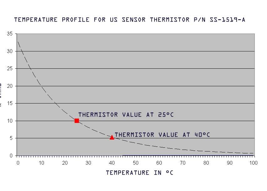
Нам показалось, что интересно ещё раз посмотреть как эта проблема решается у наших зарубежных коллег. Предлагаемая в статье наших датских друзей схема устройства контроля за работой вентилятора достаточно проста и основана на обычной схеме компаратора с изменяющимся элементом - резистором, имеющим NTC (отрицательный температурный коэффициент), известного в радиотехнике как термистор. Известно, что при повышении температуры сопротивление этого элемента падает, т.е. кривая значений сопротивления имеет отрицательный характер на его рабочей характеристике. Это отражено на кривой в прилагаемых страницах. Интересно отметить, что при нормальной температуре (около 25°C ) сопротивление термистора составляет 10 ком. Делитель напряжения (см. прилагаемую схему), имеет неинвертированный (+) вход с фиксированным сопротивлением с номиналом в 10 ком. Таким образом, при нормальной комнатной температуре напряжение питания в точке соединения делится пополам и составляет 6 вольт. Термистор крепится на радиаторе известным способом с применением термопроводящей пасты.
Для тех, кому интересен полный текст статьи, автором которой является VE2HOT, предлагаем его в полной версии.
" Circuit Description
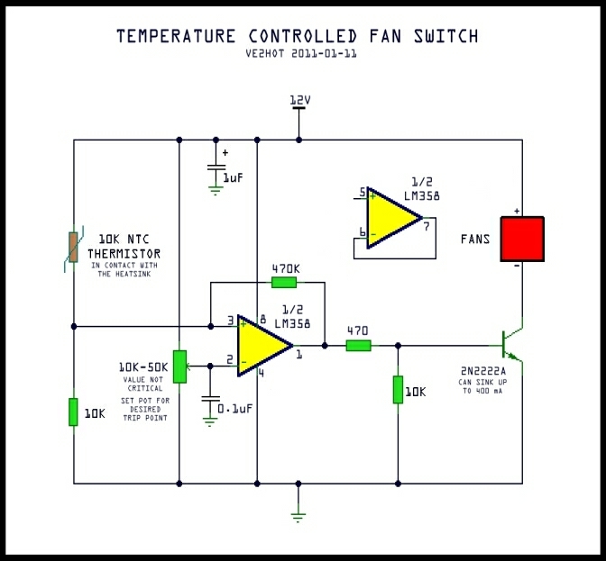
This controlled fan switch is simply a comparator circuit with the variable element beingan NTC (negative temperature coefficient) resistor, otherwise known as a thermistor. An NTC profile means the thermistor value drops as the temperature increases - hence
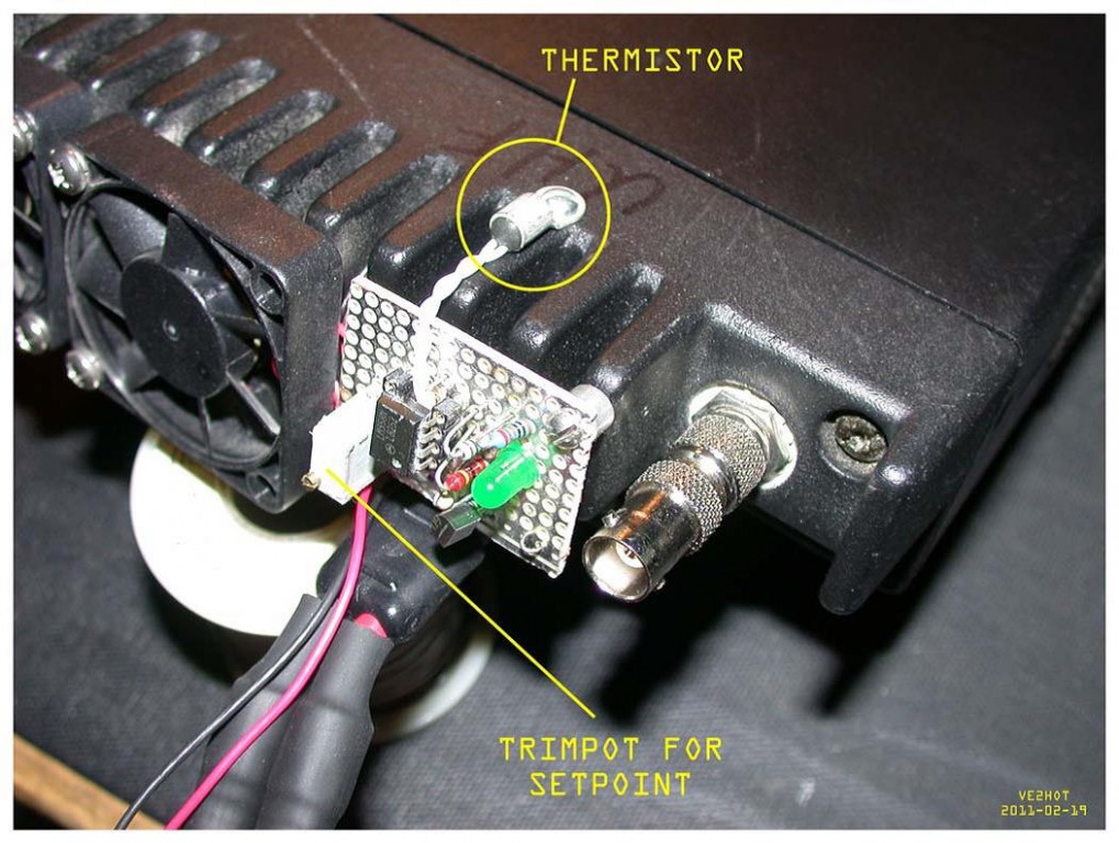
"negative". See the temperature curve in the attached pages. Note that at room temperature (25°C) the value is approximately 10K Ohms. A voltage divider is created on the non-inverting input (+) with the thermistor and a fixed 10K Ohm resistor. At room temperature the voltage the junction would be V+/2 or in this case, 6V. The inverting input (-) of the op-amp is connected to the wiper of a pot which is wired between the supply just as the network on the + input. Moving the pot will vary the
voltage on the inverting input thus setting the trip point (or reference) for the comparator. The cap on the wiper is a filter to make sure the reference signal is clean. Once the voltage on the non-inverting input exceeds the reference voltage as set by the pot, the op-amp output will toggle high. With the op-amp specified, the 470 Ohm series resistor will supply approximately 20mA into the transistor base. A typical NPN small signal transistor like a 2N2222 has a guaranteed DC gain (hfe) of about 30 @ 500 mA of collector current. This means that with 20 mA of drive, the transistor should be able to comfortably sink 600mA. The 10K resistor from the base to ground takes care of any leakage current when the transistor is not being driven. The 470K resistor from the op-amp output back to the + input provides a degree of hysteresis. This resistor introduces positive feedback which means the circuit will trip at the set point but will shut off at a lower point - how low will depend on the value of the feedback resistor. The design goal was for a 15°C differential so the value ended up
being 150K - this value was obtained empirically. The test circuit was set to trip at 50°C but only shut down at 35C. With the value shown in the schematic (470K) there is approximately 5°C of hysteresis.
Setting the Trip Point:
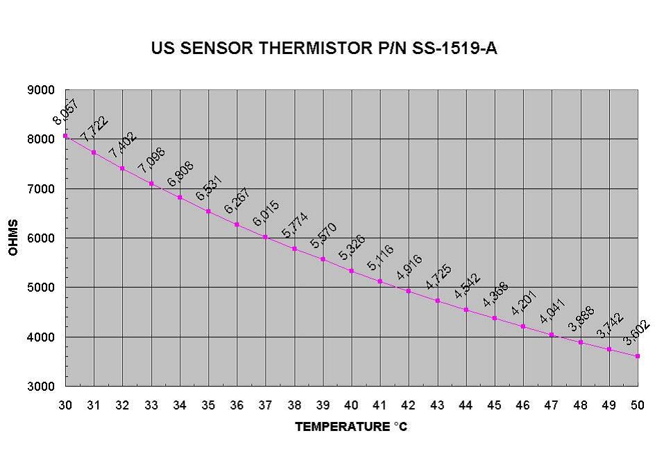
There are several ways to set the "on termperature" for the fans, but the best way is to look at the attached temperature vs. value curves and then determine what the value is at the temperature the fan should come on. Let's take an example where the fans should
come on at 50°C. The thermistor value @ 50C = 3.60K, therefore with the fixed 10K resistor, the voltage at the non-inverting input would be: (R2/(R1+R2)) *12 = 8.82V. Using a high impedance voltmeter or DMM, set the voltage on the inverting input to 8.82V by adjusting the trim pot. This method should provide a fairly close setpoint to the desired temperature. Note that depending on the value of the resistor in the feedback path, the setpoint might have to be adjusted slightly.